

How Does Grid-Scale Battery Storage Support Modern Power Systems?
Time : Sep 07, 2026 View : 290
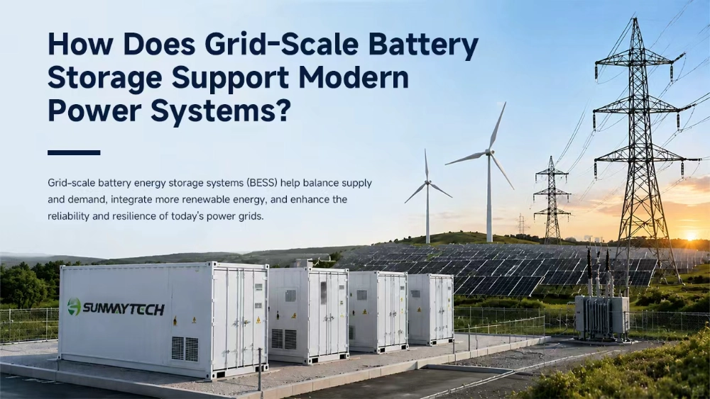
Grid scale battery storage is a controllable power-system asset that can absorb electricity, hold it for later use, and return it when the grid needs energy or a change in power. Its role extends beyond storing surplus solar or wind generation. A project may also follow dispatch instructions, support frequency or voltage, manage a local constraint, or reserve capacity for specific operating events. The useful question is not simply how large the battery is, but how its power, energy, controls, and grid connection work together.
What Makes Grid-Scale Battery Storage Different?
Commercial storage usually serves a building, factory, or campus behind the customer meter. Grid-scale battery storage normally operates as a front-of-meter asset or as part of a power station. Its charging and discharging decisions may follow utility instructions, market schedules, renewable output, or network conditions rather than one site’s electricity bill.
The distinction is based on duty and connection, not one universal capacity threshold. A large factory battery can remain behind the meter, while a smaller installation at a constrained substation may perform a grid function. Protection, metering, transformer design, communications, and interconnection rules all affect what the plant can do.
How Does Electricity Move Through a Grid-Scale BESS?
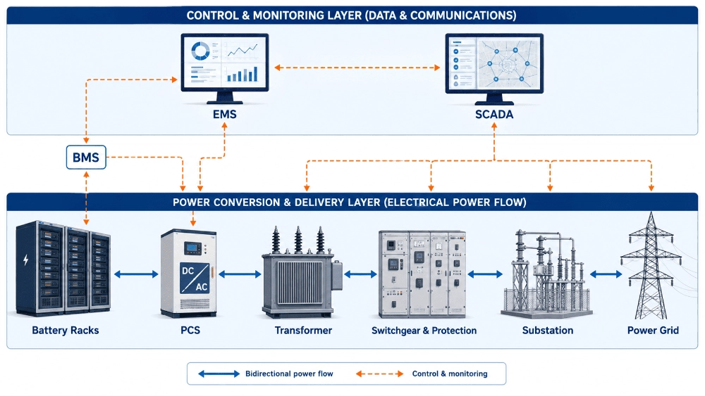
Power follows an electrical path, while dispatch instructions follow a control path. Both must remain coordinated. A valid command cannot produce the intended response if the battery, PCS, transformer, switchgear, or grid connection has reached a limit.
The charging path
During charging, electricity may come from the grid or a nearby solar or wind plant. In an AC-coupled layout, AC power reaches the power conversion system through the connection equipment. The PCS converts it to DC within battery voltage and current limits. DC-coupled renewable plants use a different conversion path. The battery management system checks cell voltage, temperature, current, state of charge, and faults before permitting the request.
Charging is not always tied to low prices. A plant may absorb renewable output that would otherwise be curtailed, follow a dispatch schedule, or create room before an expected generation peak. The target determines how much capacity must remain available.
The discharging path
During discharge, the process reverses. The battery supplies DC power within limits set by the BMS. The PCS converts that power to grid-compatible AC and controls active and reactive output. Electricity then passes through switchgear, metering, protection devices, and usually a step-up transformer before reaching the substation or interconnection point.
The plant cannot simply export any requested value. PCS rating, battery condition, transformer capacity, auxiliary consumption, protection settings, and the interconnection agreement establish the practical boundary. Nameplate energy alone does not confirm deliverable power at the grid connection.
The control path
A utility, market platform, or plant controller may issue an operating target. The EMS translates it into a charge, discharge, standby, or reserve instruction. SCADA provides plant status, alarms, and operator communication. The BMS defines the safe battery boundary, and the PCS executes the approved command.
If an EMS request exceeds the power permitted by battery temperature or state of charge, the safe limit takes priority. A grid target cannot override battery protection. The same hierarchy applies to reactive power, voltage, power-factor control, and export limits.
Which Grid Energy Storage Applications Need Different Operating Modes?
Grid energy storage applications do not place the same demand on the battery. Some move energy for hours, while others require frequent changes in power. A project specification should identify the primary duty and explain how secondary duties share capacity.
Energy shifting and renewable integration
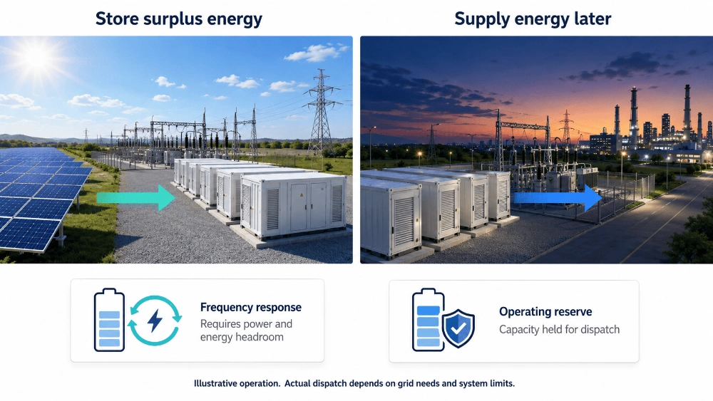
Energy shifting stores electricity in one period and releases it in another. With solar or wind, a battery can absorb part of a production surplus and discharge after output falls. The value of grid scale battery storage for renewable energy depends on generation, grid capacity, curtailment, dispatch rules, and duration.
Battery storage for renewable energy does not make variable generation continuous. Stored energy is finite, and extended low-output periods may exceed the planned discharge window. Forecasts and reserve settings remain important.
Frequency response and operating reserves
Frequency support requires active-power changes in response to a grid signal. The system may increase discharge, reduce charging, or absorb additional power, depending on the event and market rules. Operating reserves also require capacity to be held back rather than used for routine energy trading.
These services need approved controls, reliable communication, suitable metering, and headroom in both directions. A full battery cannot absorb much more energy, while one at minimum state of charge cannot sustain further discharge.
Voltage and network support
The PCS may regulate reactive power or work toward a voltage or power-factor target when the equipment and grid agreement allow it. Active and reactive power are separate control variables. Power-factor control is a target achieved mainly by changing reactive power; it does not replace active-power dispatch.
Other grid energy storage applications include peak capacity, congestion management, and ramp control. Black start, island operation, and seamless transfer must not be assumed. They require grid-forming capability, switching equipment, protection logic, auxiliary power, and an approved sequence.
Why Do MW, MWh, and Duration Matter Separately?
MW measures power: how quickly the system can charge or discharge. MWh measures energy: how much electricity is available over time. Duration links them. At a simplified level, usable energy divided by discharge power gives operating hours at that power, before losses and reserve requirements are considered.
This is why MW vs MWh in battery storage is a project-design question rather than a terminology issue. Frequency response may require high power with limited energy movement. Evening renewable shifting may require a longer discharge period. A system designed for one duty may not have the appropriate power-to-energy ratio for another.
MW vs MWh for grid scale battery storage must be assessed at the correct point. PCS output, transformer losses, auxiliary loads, usable state-of-charge range, and reserve affect what reaches the grid. Buyers should compare guaranteed performance under defined operating conditions, not cabinet capacity alone.
How Is Utility-Scale Battery Storage Connected and Controlled?
An electrical connection establishes the physical boundary; the control architecture determines how the plant behaves within it. Both must be designed around the same grid code, operating duty, and responsibility split.
Electrical connection and protection
The typical connection includes battery enclosures or containers, PCS units, transformers, medium- or high-voltage switchgear, protection relays, meters, auxiliary power, and a substation interface. The exact arrangement depends on project voltage, capacity, site layout, redundancy, and local requirements.
Protection should isolate faults without unnecessary plant-wide trips. Metering must support settlement and performance checks. Where export is restricted, reverse-power control uses meters and control logic to detect direction and adjust output before the agreed limit is crossed.
Dispatch, supervision, and operating limits
EMS, SCADA, BMS, and PCS form linked but distinct control layers. A clear explanation of the roles of PCS, BMS, and EMS helps prevent overlapping specifications. SCADA then adds plant-level supervision, operator access, event records, and communication with external control systems.
Control design should define command ownership, limit priority, communication-loss behavior, and return to service after a trip. It should also state whether active power, reactive power, voltage, frequency, or power factor is controlled. Similar labels can describe different duties.
What Limits Real-World Grid Storage Performance?
Utility-scale battery storage cannot assign the same capacity to every service at the same time. Energy reserved for an evening peak is unavailable for an earlier discharge unless the schedule changes. Headroom reserved for frequency response may reduce energy-trading volume. Service stacking therefore needs explicit priorities.
Temperature, state of charge, cell balance, ageing, PCS limits, transformer loading, and auxiliary demand can reduce output. Repeated cycling changes usable capacity. Capacity augmentation, reserve, maintenance access, and availability guarantees should be considered before the layout is fixed.
Grid conditions create another boundary. Interconnection terms, market rules, communications, or metering may prevent an otherwise capable plant from providing a service. Grid-forming operation, voltage support, and restoration functions require separate engineering and approval.
What Should Developers Define Before System Selection?
Before comparing equipment, a project team should define:
- the primary service and any secondary revenue or reliability duties;
- required MW, usable MWh, discharge duration, and reserve state of charge;
- expected cycles, ramp pattern, and charging input;
- grid voltage, point of interconnection, export limits, and protection scope;
- active-power, reactive-power, voltage, and power-factor requirements;
- EMS and SCADA interfaces, communication-loss behavior, and data ownership;
- environmental limits, thermal management, fire protection, and service access;
- degradation assumptions, augmentation strategy, and performance test method.
At SUNWAY, we use these project inputs to narrow the architecture before equipment ratings are selected. Developers can review broader utility-scale energy storage options once the operating duty and grid interface are clear.
Conclusion
Grid scale battery storage supports modern power systems by moving energy in time and changing power in response to network needs. Its performance depends on more than battery capacity. PCS capability, transformers, protection, controls, metering, reserve strategy, and grid approval all shape the usable result.
A sound project starts with a defined service, a realistic MW-to-MWh relationship, and a clear command hierarchy. For support translating those requirements into a system architecture, discuss the required operating duty with our project team.
FAQ
Q: How does grid scale battery storage work?
A: It charges from the grid or a generation plant, stores energy in batteries, and discharges through a PCS when instructed. EMS and SCADA coordinate the target, while the BMS keeps operation within safe battery limits.
Q: How is utility-scale battery storage connected to the grid?
A: A project normally connects through PCS equipment, transformers, switchgear, protection relays, meters, and a defined interconnection point. The design depends on voltage, capacity, local grid rules, protection, and the required services.
Q: Why are both MW and MWh needed when specifying grid storage?
A: MW defines charging or discharging power. MWh defines stored energy over time. Both are needed because fast grid services and longer energy shifting impose different power, energy, reserve, and cycling requirements.