

Системы управления питанием (PCS), системы управления батареями (BMS) и системы управления энергопотреблением (EMS) в системах хранения энергии для коммерческих и промышленных предприятий: что контролирует каждая система.
Время: 27 июля 2026 г. Просмотров: 669
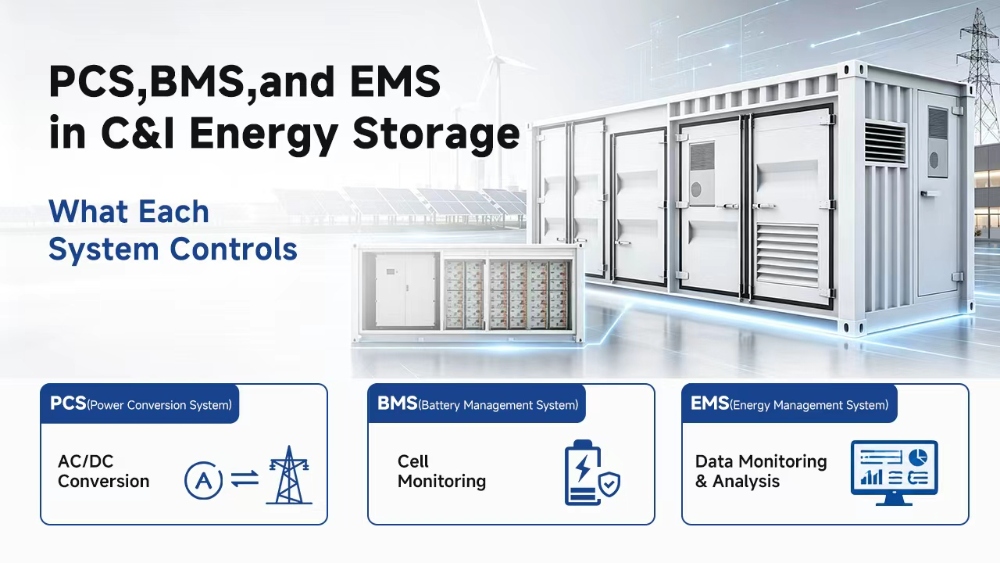 В коммерческом батарейном шкафу могут содержаться подходящие батарейные элементы, достаточная емкость системы управления питанием (PCS) и функциональное программное обеспечение управления, однако проект все равно может работать плохо, если его уровни управления не скоординированы. Системы PCS, BMS и EMS часто группируются в технической спецификации, но каждая из них выполняет разные функции.
Система управления питанием (PCS) передает электрическую энергию. Система управления батареей (BMS) защищает батарею и устанавливает безопасные пределы. Система управления энергоснабжением (EMS) определяет, когда система должна заряжаться, разряжаться, ждать или сохранять резервную энергию. В системе хранения энергии на основе батарей эти функции должны обмениваться точными данными и командами в правильной последовательности. В этом руководстве объясняется каждая роль, где обязанности пересекаются и что покупатели должны проверить, прежде чем утверждать интегрированное решение для хранения энергии для коммерческих и промышленных предприятий.
Почему важны границы контроля в системах хранения энергии для коммерческих и промышленных предприятий?
Шкаф для промышленных и производственных целей объединяет в себе функции хранения энергии, преобразования мощности, контроля состояния батарей, планирования работы объекта, терморегулирования, защиты и связи.
Четкие границы предотвращают противоречивые решения. Система управления энергоснабжением (EMS) может запросить разрядку, если завод приближается к пределу потребления. Система управления батареями (BMS) может снизить допустимую мощность из-за повышения температуры элементов. Система управления питанием (PCS) должна следовать безопасному значению, а не первоначальной коммерческой цели.
Плохая координация может привести к неполным данным о состоянии заряда, задержкам в реагировании, неоправданному снижению мощности или неясным процедурам перезапуска. Проекты с использованием оборудования разных производителей требуют особого внимания, поскольку совместимость оборудования не гарантирует полной совместимости команд и сигналов тревоги.
Та же иерархия наблюдается и в бытовые системы хранения энергииОднако коммерческим объектам необходимы более детальный контроль нагрузки, планирование тарифов, трехфазная координация и интеграция электростанций.
Что контролирует каждая система?
Система управления питанием (PCS) отвечает за преобразование и вывод сигнала, система управления батареей (BMS) контролирует работу батареи, а система управления энергопотреблением (EMS) координирует задачи объекта.
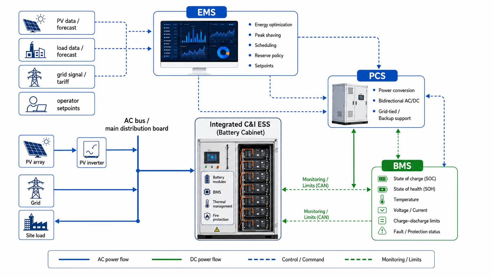
PCS управляет преобразованием и выходной мощностью.
PCS расшифровывается как система преобразования энергии. Она преобразует постоянный ток от батареи в переменный ток для нагрузок или сети, а также преобразует переменный ток в постоянный, когда батарея заряжается от сети.
Система управления зарядом (PCS) выполняет команды заряда и разряда в пределах номинальных параметров мощности, тока, напряжения и температуры. Она также может управлять активной и реактивной мощностью, синхронизацией с сетью и защитными мерами. В автономном режиме работы она может поддерживать местное переменное напряжение и частоту.
Мощность PCS, измеряемая в кВт, определяет скорость зарядки или разрядки системы. Емкость батареи, измеряемая в кВт·ч, указывает на количество накопленной энергии. Большая батарея не гарантирует автоматическую поддержку любой запрашиваемой мощности; номинальная мощность PCS, ограничения батареи, продолжительность разряда и профиль нагрузки должны совпадать.
Система управления батареей (BMS) контролирует ограничения и защиту батареи.
BMS расшифровывается как система управления батареей. Она контролирует состояние батареи и поддерживает ее работу в пределах допустимых электрических и тепловых параметров.
Система управления батареей (BMS) собирает данные о напряжении, токе и температуре от ячеек, модулей или батарейных блоков. Она отслеживает уровень заряда и может оценивать состояние батареи. Она также выявляет электрические, тепловые, изоляционные и коммуникационные неисправности.
Его ключевая роль заключается в передаче допустимых пределов заряда и разряда. Эти значения изменяются в зависимости от температуры, напряжения и состояния заряда. При приближении к пороговому значению защиты система управления батареей (BMS) может выдать сигнал тревоги, запросить снижение мощности или запустить механизм автоматического отключения.
Система управления батареей (BMS) не решает, когда цены на электроэнергию выгодны или когда заводу следует сократить потребление. Она решает, может ли батарея безопасно выполнить запрошенную команду.
EMS контролирует операционную стратегию.
EMS расшифровывается как система управления энергопотреблением. Она преобразует цели проекта в графики зарядки и разрядки.
Система управления энергоснабжением (EMS) может объединять данные о нагрузке, выработке солнечной энергии, тарифных периодах, состоянии сети, состоянии батарей и требованиях к резервам. Затем она принимает решение о том, когда система должна заряжаться, разряжаться, оставаться в режиме ожидания или сохранять энергию для резервного питания. Это делает ее центральным элементом в сглаживании пиковых нагрузок, управлении спросом, самопотреблении солнечной энергии и работе в зависимости от времени суток.
Стратегия должна соответствовать особенностям местности. Завод может отдавать приоритет ограничению спроса, в то время как отель может сохранять резервную энергию на вечер. Склад с солнечными батареями на крыше может накапливать избыток энергии в полдень и разряжать его после захода солнца. Поэтому для коммерческих систем хранения энергии необходима логика управления, специфичная для данной местности.
В каких областях обязанности служб PCS, BMS и EMS пересекаются?
Их решения взаимосвязаны, поэтому покупателям следует изучить пути управления, передачи данных и защиты.
Система EMS запрашивает электропитание, но система BMS устанавливает границы допустимого диапазона.
Например, во время пиковой нагрузки производства во второй половине дня система управления батареей (EMS) может запросить разряд мощностью 80 кВт. Система управления батареей (BMS) проверяет состояние заряда, температуру, разброс напряжения и допустимую токовую нагрузку. Если батарея может безопасно поддерживать только 60 кВт, приоритет должен отдаваться меньшему значению.
Система управления питанием (PCS) выполняет утвержденную команду. По мере изменения состояния батареи, система управления батареей (BMS) обновляет ограничение, а система управления энергопотреблением (EMS) пересматривает свой план. Та же логика применяется и во время зарядки: EMS определяет недорогую электроэнергию из сети или избыточную солнечную энергию, BMS подтверждает, какую мощность может принять батарея, и PCS передает мощность в пределах этого диапазона.
Сигнализация, снижение мощности и отключение — это разные вещи.
Сигнал тревоги регистрирует нештатную ситуацию и оповещает операторов, но работа может продолжаться. Снижение номинальной мощности уменьшает мощность заряда или разряда, пока система остается в сети. Отключение останавливает подсистему или всю систему, если продолжение работы превысит допустимый предел защиты.
В спецификации управления следует указать этапы обнаружения, реагирования, выполнения PCS, записи EMS, а также режим восстановления: автоматический или ручной.
Как работают три системы в течение полного цикла?
Один рабочий цикл демонстрирует, как управляющие слои поддерживают друг друга.
От зарядки в полдень до пикового вечернего бритья
В полдень выработка солнечной энергии превышает нагрузку объекта. Система управления энергоснабжением (EMS) выявляет избыток выработки и отправляет запрос на зарядку. Система управления батареей (BMS) подтверждает состояние батареи, температуру, диапазон напряжения и допустимый ток. Затем система управления питанием (PCS) передает мощность с утвержденной скоростью.
Позже спрос на электроэнергию возрастает. Система управления энергоснабжением (EMS) запрашивает сброс электроэнергии, чтобы поддерживать импорт из сети ниже целевого уровня. Система управления зданием (BMS) подтверждает допустимый уровень, и система управления питанием (PCS) подает переменный ток на объект.
Если проект требует сохранения резервной энергии, система управления энергоснабжением (EMS) прекращает экономически целесообразный разряд при достижении зарезервированного уровня заряда. Эта политика должна быть установлена до ввода в эксплуатацию, поскольку экономия в пиковые периоды и готовность к резервному электроснабжению конкурируют за одну и ту же накопленную энергию.
При изменении температуры или состояния электросети
При повышении температуры батареи система управления батареей (BMS) может снизить допустимую мощность. Реакция также зависит от того, используется ли в проекте... коммерческие системы хранения энергии с воздушным или жидкостным охлаждениемПоскольку каждая архитектура по-разному управляет тепловыделением, плотностью размещения шкафов и техническим обслуживанием, система терморегулирования увеличивает охлаждение, система управления питанием (PCS) снижает мощность при необходимости, а система управления энергопотреблением (EMS) корректирует график работы.
Если напряжение или частота сети выходят за пределы допустимого диапазона, блок управления питанием (PCS) может отключиться или изменить режим работы в соответствии с утвержденными настройками защиты. Система управления энергоснабжением (EMS) регистрирует это событие и координирует стратегию резервирования, если блок управления питанием, распределительное устройство и архитектура объекта поддерживают непрерывное электроснабжение.
Записи о событиях помогают сервисным группам определять пределы возможностей батарей, защиту PCS, сбои в сети и сбои связи.
Что следует проверить покупателям перед заказом интегрированной системы хранения энергии?
Поставщик должен объяснить, как система ведет себя в нормальном режиме работы, при возникновении неисправностей, техническом обслуживании и расширении.
Протоколы связи и точки данных
Одних только названий протоколов недостаточно. CAN, RS485 и Ethernet описывают методы связи, но покупателям по-прежнему необходим список точек данных и права доступа к управлению.
Система управления батареей (BMS) должна передавать в PCS и EMS информацию о состоянии заряда, напряжении, токе, температуре, аварийных сигналах и допустимой мощности. EMS также может потребоваться информация с бортовых счетчиков, данные о выработке фотоэлектрической энергии, потребляемой нагрузке и состоянии сети.
При подключении к SCADA-системам или платформам сторонних производителей необходимо подтвердить карты адресов, частоту обновления, синхронизацию времени, права доступа и иерархию управления.
Управление логикой, доступом и расширением
Перед утверждением покупатели, сравнивающие коммерческие системы хранения энергии на основе аккумуляторов, должны запросить последовательность операций зарядки, сглаживания пиковых нагрузок, управления резервом и восстановления после сбоев. В документации следует четко указать предупреждения, условия снижения мощности, пороговые значения отключения и события ручного сброса.
Удаленный доступ должен осуществляться с использованием четко определенных прав доступа. Операторам необходимы данные о мощности, состоянии заряда, температуре, аварийных сигналах и потоке энергии в режиме реального времени, а изменения параметров должны контролироваться и регистрироваться.
Добавление аккумуляторных шкафов или модулей PCS может потребовать новых адресов, пересмотра ограничений, обновления настроек защиты и расширения диапазона диспетчеризации EMS. Модульный шкаф полезен только в том случае, если платформа управления может управлять дополнительной мощностью.
Как интегрированная система хранения энергии мощностью 100 кВт/232 кВт⋅ч применяет эти механизмы управления?
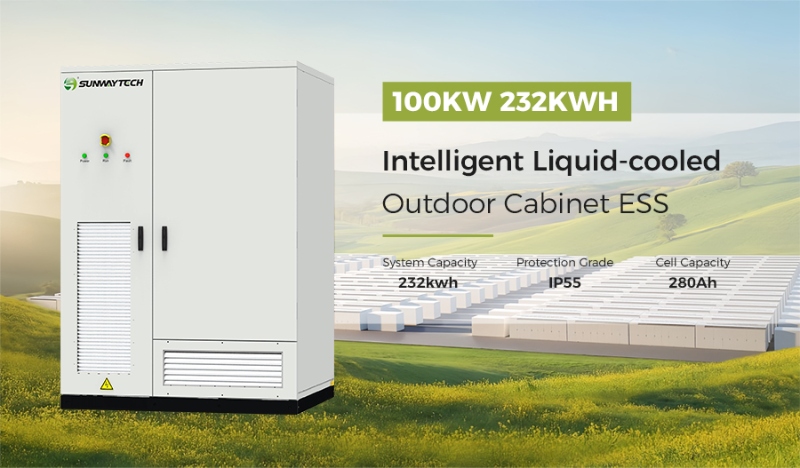
Интегрированный шкаф позволяет упростить координацию интерфейсов, поскольку функции батареи, преобразования, управления, охлаждения, защиты и распределения объединены в единую платформу.
В СанвейМы настраиваем системы с учетом требований проекта к мощности, энергопотреблению, сети, площадке и эксплуатации. Выбор по-прежнему зависит от проверенных данных о нагрузке, местных стандартов и определенной стратегии управления.
Интегрированные элементы управления сокращают объем работы по взаимодействию с интерфейсами.
Он Интегрированная система хранения энергии для промышленных и коммерческих объектов мощностью 100 кВт/232 кВт·ч В наружном корпусе объединены литий-железо-фосфатный аккумулятор емкостью 232 кВт·ч, модульная система управления питанием (PCS), система управления батареями (BMS), система управления энергопотреблением (EMS), система распределения питания, система контроля окружающей среды и функции пожарной безопасности. Обеспечивает номинальную мощность переменного тока 100 кВт и номинальную входную мощность фотоэлектрической системы 100 кВт через два канала MPPT.
Для связи с системой управления зданием (BMS) используется протокол CAN, а для связи с системой управления электроникой (EMS) — Ethernet/485. Корпус со степенью защиты IP55 использует интеллектуальное жидкостное охлаждение и работает в диапазоне температур от -25°C до +60°C, при этом снижение номинальной мощности происходит при температуре выше 45°C.
Эти значения связывают логику управления с физическими ограничениями. Система управления энергопотреблением (EMS) планирует работу, система управления питанием (PCS) выполняет команды управления мощностью в пределах номинальной мощности, а система управления батареей (BMS) контролирует ограничения батареи.
Модульная конструкция обеспечивает поддержку процессов доставки и обслуживания.
Модульная конструкция PCS обеспечивает удобство технического обслуживания и возможность внесения изменений в конфигурацию в будущем. Доступ к сервисной зоне спереди позволяет уменьшить дорожный просвет сзади при выполнении плановых работ, а заводская сборка и тестирование упрощают задачи по интеграции на объект.
Эти преимущества не заменяют инженерные решения. Защита сети, правила пожарной безопасности, проектирование кабелей, схемы коммуникаций и ввод в эксплуатацию по-прежнему должны соответствовать местным требованиям.
Выбирайте систему по логике управления, а не по названиям компонентов.
Системы управления питанием (PCS), управления батареями (BMS) и управления энергоснабжением (EMS) следует рассматривать как скоординированную цепочку. Система PCS осуществляет преобразование энергии, BMS определяет безопасные пределы заряда батарей, а EMS преобразует задачи объекта в графики работ.
Хорошо интегрированная система хранения энергии на основе батарей обеспечивает точные данные, четкий приоритет команд, документированные реакции защиты и пригодные для использования записи событий. Покупателям следует сравнивать архитектуру, точки связи, логику управления и ответственность за обслуживание, а также показатели в кВт и кВт·ч.
Предоставьте нам информацию о нагрузочной кривой, пиковой нагрузке, мощности фотоэлектрических систем, целевом резервном источнике питания, напряжении сети и необходимых интерфейсах. Мы сможем проанализировать, как должны взаимодействовать три уровня управления, и помочь вам. запросить проверку системы управления для практической коммерческой конфигурации системы хранения энергии.
Часто задаваемые вопросы
В: В чем разница между PCS, BMS и EMS в системе хранения энергии на основе батарей?
A: Система управления питанием (PCS) осуществляет двунаправленное преобразование энергии. Система управления батареей (BMS) контролирует состояние батареи и устанавливает безопасные пределы заряда и разряда. Система управления энергоснабжением (EMS) планирует работу на основе нагрузки, тарифов, выработки фотоэлектрической энергии, состояния сети и целевых показателей резерва.
В: Может ли система хранения энергии для коммерческих и промышленных предприятий работать без системы управления энергоснабжением?
А: Некоторое оборудование может работать с локальным управлением, но возможности сглаживания пиковых нагрузок, координации солнечной активности, планирования тарифов, управления несколькими шкафами, удаленного мониторинга и управления резервами могут быть ограничены.
В: Какие протоколы связи следует проверять покупателям в коммерческих системах хранения энергии на основе аккумуляторов?
A: К распространенным протоколам относятся CAN, RS485 и Ethernet. Покупателям также следует проверить точки данных, скорость обновления, права доступа к командам, поведение при сбоях, интеграцию со сторонними сервисами и поддержку расширения.